
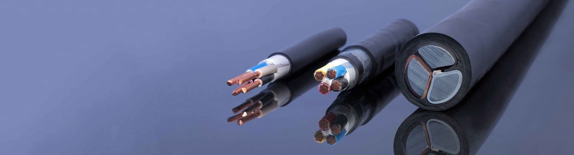

Uzbekistan Copper Solar Panels AC DC Photovoltaic Wire Solar PV Cable
Category:
UzbekistanNew Energy
Product Description
Application
Solar cable also called photovoltaic cable, they are series cables between photovoltaic modules and modules on the DC side of the photovoltaic power generation system, parallel cables between strings and between strings and DC distribution boxes (combiner boxes), and DC distribution boxes to inverters. It can also be used for AC application cables for the connection between the inverter and the transmission grid. Photovoltaic cables supporting other photovoltaic modules are exported to Europe, and the cables must comply with the TUV MARK certificate issued by TUV Rheinland, Germany.
Executive Standard
NB/T 42073- 2016 Cables for Photovoltaic Power Generation Systems (National Energy Administration)
COC 1102- 2016 Technical Specifications for Certification of Cable Products for Photovoltaic Power Generation Systems (China Quality Certification Center)
2PfG 1169/08.2007 PV cable (cable for photovoltaic modules) technical specification (TUV Rheinland, Germany)
EN 50618: 2014 Cable Standard for Photovoltaic Systems (EU)
Technical Specification
-Cable cables are widely used in electrical installation lines for indoor and outdoor solar installations;
-Features: Low-Smoke and Halogen-Free, excellent cold resistance, UV resistance, ozone resistance and weather resistance. Flame retardant, cut resistance, penetration resistance;
-Ambient temperature: -40℃~+90℃; Maximum conductor temperature: 120℃(short-circuit temperature of 200℃ within 5s is allowed);
-Rated voltage: AC 0.6/1kV, DC 1.8kV;
-Design life: 25 years.
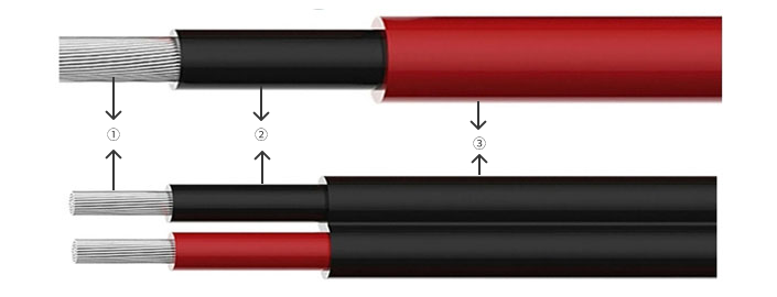
Construction
① Conductor: Flexible Tinned copper Class 5 (K) as per EN 60228
② Insulation: Halogen-free cross-linked LS0H-XL compound
③ Jacket: Halogen-free cross-linked LS0H-XL compound
Technical Parameter
2PfG 1169/08.2007 Standard
The insulation thickness is specified by the manufacturer, but the minimum value must be ≥ 0.5mm. Recommended insulation thickness, as shown in Table 1 below:
Table 1 2PfG 1169/08.2007 Insulation Nominal Thickness (Recommended)
| Nominal Cross Section(mm2) | 1.5 | 2.5 | 4 | 6 | 10 | 16 | 25 | 35 |
| Insulation Nominal Thickness(mm) | 0.8 | 0.8 | 1.0 | 1.0 | 1.0 | 1.0 | 1.2 | 1.2 |
The sheath thickness is specified by the manufacturer, but the minimum value must be ≥ 0.5mm. Recommended insulation thickness, as shown in Table 2 below:
Table 2 2PfG 1169/08.2007 Sheath Nominal Thickness (Recommended)
| Nominal Cross Section(mm2) | 1.5 | 2.5 | 4 | 6 | 10 | 16 | 25 | 35 |
| Sheath Nominal Thickness(mm) | 0.8 | 0.8 | 0.9 | 0.9 | 0.9 | 1.1 | 1.2 | 1.2 |
EN 50618:2014 Standard
Table 3 EN 50618:2014 Dimensions and values of insulation resistance
| Core number x Cross Sectionmm2 | Nominal Insulation thicknessmm | Nominal Sheath thicknessmm | Average Max.O.Dmm | Min. Insulation Resistance at 20℃MΩ.km | Min. Insulation Resistance at 90℃MΩ.km |
| 1×1.5 | 0.7 | 0.8 | 5.4 | 859 | 0.859 |
| 1×2.5 | 0.7 | 0.8 | 5.9 | 691 | 0.691 |
| 1×4 | 0.7 | 0.8 | 6.6 | 579 | 0.579 |
| 1×6 | 0.7 | 0.8 | 7.4 | 499 | 0.499 |
| 1×10 | 0.7 | 0.8 | 8.8 | 424 | 0.424 |
| 1×16 | 0.7 | 0.9 | 10.1 | 342 | 0.342 |
| 1×25 | 0.9 | 1.0 | 12.5 | 339 | 0.339 |
| 1×35 | 0.9 | 1.1 | 14.0 | 287 | 0.287 |
| 1×50 | 1.0 | 1.2 | 16.3 | 268 | 0.268 |
| 1×70 | 1.1 | 1.2 | 18.7 | 247 | 0.247 |
| 1×95 | 1.1 | 1.3 | 20.8 | 220 | 0.220 |
| 1×120 | 1.2 | 1.3 | 22.8 | 211 | 0.211 |
| 1×150 | 1.4 | 1.4 | 25.5 | 206 | 0.206 |
| 1×185 | 1.6 | 1.6 | 28.5 | 200 | 0.200 |
| 1×240 | 1.7 | 1.7 | 32.1 | 198 | 0.198 |
NB/T 42073-2016 Standard
Table 4 Comprehensive data of single core cable
| Core number x Cross Sectionmm2 | Nominal Insulation thicknessmm | Nominal Sheath thicknessmm | Average Max.O.Dmm | Min. Insulation Resistance at 20℃MΩ.km | Min. Insulation Resistance at 90℃MΩ.km |
| 1×1.5 | 0.7 | 0.8 | 5.4 | 860 | 0.86 |
| 1×2.5 | 0.7 | 0.8 | 5.9 | 690 | 0.69 |
| 1×4 | 0.7 | 0.8 | 6.6 | 580 | 0.58 |
| 1×6 | 0.7 | 0.8 | 7.4 | 500 | 0.50 |
| 1×10 | 0.7 | 0.8 | 8.8 | 420 | 0.42 |
| 1×16 | 0.7 | 0.9 | 10.1 | 340 | 0.34 |
| 1×25 | 0.9 | 1.0 | 12.5 | 340 | 0.34 |
| 1×35 | 0.9 | 1.1 | 14.0 | 290 | 0.29 |
| 1×50 | 1.0 | 1.2 | 16.3 | 270 | 0.27 |
| 1×70 | 1.1 | 1.2 | 18.7 | 250 | 0.25 |
| 1×95 | 1.1 | 1.3 | 20.8 | 220 | 0.22 |
| 1×120 | 1.2 | 1.3 | 22.8 | 210 | 0.21 |
| 1×150 | 1.4 | 1.4 | 25.5 | 210 | 0.21 |
| 1×185 | 1.6 | 1.6 | 28.5 | 200 | 0.20 |
| 1×240 | 1.7 | 1.7 | 32.1 | 200 | 0.20 |
Table 5 Comprehensive data of multi core cable
| Core number x Cross Sectionmm2 | Nominal Insulation thicknessmm | Nominal Sheath thicknessmm | Average Min.O.Dmm | Average Max.O.Dmm | Min. Insulation Resistance at 20℃MΩ.km | Min. Insulation Resistance at 90℃MΩ.km |
| 2×1.5 | 0.7 | 0.9 | 7.0 | 9.1 | 860 | 0.86 |
| 2×2.5 | 0.7 | 0.9 | 7.9 | 10.2 | 690 | 0.69 |
| 2×4 | 0.7 | 1.0 | 9.1 | 11.8 | 580 | 0.58 |
| 2×6 | 0.7 | 1.1 | 10.3 | 13.2 | 500 | 0.50 |
| 2×10 | 0.7 | 1.2 | 12.2 | 15.6 | 420 | 0.42 |
| 2×16 | 0.7 | 1.3 | 14.5 | 18.5 | 340 | 0.34 |
| 3×1.5 | 0.7 | 1.0 | 7.7 | 10.0 | 098 | 0.86 |
| 3×2.5 | 0.7 | 1.1 | 8.7 | 11.3 | 690 | 0.69 |
| 3×4 | 0.7 | 1.2 | 10.1 | 13.0 | 580 | 0.58 |
| 3×6 | 0.7 | 1.2 | 11.1 | 14.3 | 500 | 0.50 |
| 3×10 | 0.7 | 1.2 | 13.0 | 16.7 | 420 | 0.42 |
| 3×16 | 0.7 | 1.3 | 15.4 | 19.7 | 340 | 0.34 |
| 4×1.5 | 0.7 | 1.1 | 8.5 | 11.0 | 860 | 0.86 |
| 4×2.5 | 0.7 | 1.2 | 9.8 | 12.6 | 690 | 0.69 |
| 4×4 | 0.7 | 1.2 | 11.0 | 14.2 | 580 | 0.58 |
| 4×6 | 0.7 | 1.2 | 12.3 | 15.7 | 500 | 0.50 |
| 4×10 | 0.7 | 1.3 | 14.5 | 18.5 | 420 | 0.42 |
| 4×16 | 0.7 | 1.4 | 17.3 | 22.0 | 340 | 0.34 |
| 5×1.5 | 0.7 | 1.2 | 9.5 | 12.2 | 860 | 0.86 |
| 5×2.5 | 0.7 | 1.2 | 10.7 | 13.8 | 690 | 0.69 |
| 5×4 | 0.7 | 1.3 | 12.3 | 15.7 | 580 | 0.58 |
| 5×6 | 0.7 | 1.3 | 13.6 | 17.4 | 500 | 0.50 |
| 5×10 | 0.7 | 1.4 | 16.1 | 20.5 | 420 | 0.42 |
| 5×16 | 0.7 | 1.6 | 19.4 | 24.6 | 340 | 0.34 |
Table 6 Current capacity of Solar cables
| Nominal Cross Sectionmm2 | Current Capacity | ||
| Single core cable in Air | Single Core Cable on the ground | Two Cores Cable on the ground | |
| 1,5 | 30 | 29 | 24 |
| 2,5 | 41 | 39 | 33 |
| 4 | 55 | 52 | 44 |
| 6 | 70 | 67 | 57 |
| 10 | 98 | 93 | 79 |
| 16 | 132 | 125 | 107 |
| 25 | 176 | 167 | 142 |
| 35 | 218 | 207 | 176 |
| 50 | 276 | 262 | 221 |
| 70 | 347 | 330 | 278 |
| 95 | 416 | 395 | 333 |
| 120 | 488 | 464 | 390 |
| 150 | 566 | 538 | 453 |
| 185 | 644 | 612 | 515 |
| 240 | 775 | 736 | 620 |
| Ambient Temperature:60℃(Other temperature in Table 7) Max. Conductor Temperature::120℃。 | |||
Table 7 Rated current conversion coefficient at different ambient temperatures(EN 50618)
| Ambient Temperature | Conversion Coefficient |
| ≤60 | 1.00 |
| 70 | 0.92 |
| 80 | 0.84 |
| 90 | 0.75 |
: next page
Quick Quote
* Note: Please be sure to fill in the information accurately and keep the communication open. We will get in touch with you as soon as possible
Copyright © 2023 Shandong Zhongmai Cable Co., Ltd